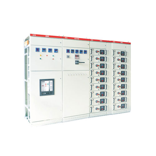
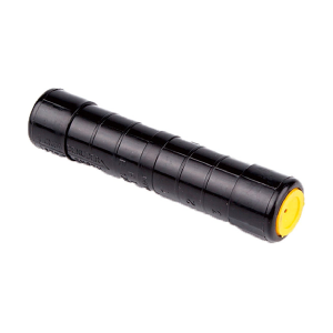
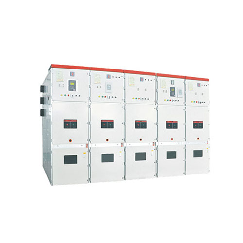
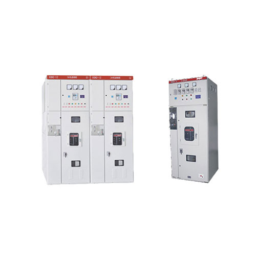
CAGCS Low Voltage Withdrawable Switchgear

Product Summary
CAGCS low Voltage withdrawable switchgear is suitable for the low voltage distribution system in power plant, petroleumindustry, chemical industry, metallurgy industry, spinning mill, high buildings, etc. It is especially used in large power plant,petrochemical system and other locations which are. required high automatic and computer interface. It is serviced in the lowvoltage apparatus distribution devices of generator and power supply system distribution, motor central control and reactive powercompensate of 3 phase AC 50/60Hz, 400V, rated current 4000A and lower.
Environmental Conditions
1.Installation Site: Indoor
2.Altitude: No more than 2000m.
3.Earthquake Intensity: No more than 8 degrees.
4.Ambient Temperature: No more than + 40℃ and no less than -15℃.Average temperature is no more than +35℃ within 24 hours.
5.Relative Humidity: the average daily value is no more than 95%, the average monthly value is no more than 90%.
6.Installation locations: without fire, explosion danger, serious pollution, chemical corrosion and violent vibration.
Product Features
1.It can be increased the thermal capacity of adaptor parts. Also it can be effectively and evidently reduced the temperature rise ofadaptor parts or additional temperature rise of cable lug and partition board.
2.The quantity of a single MCC panel s loop is up to 22 Nos., this can satisfy requirements of power plant which has high capacityof single generator, automatic motor control door (machine) set of petrochemical system and other industries.
3.The connection between the device and the external cable is completed in the cable compartment, and the cable can get in andout on the top or bottom. The zero sequence current transformer is placed in the cable compartment, so that the installation andmaintenance are convenient.
4.Drawer units have enough quantity secondary adaptors (32 pairs for 1 unit and above, 20 pairs for 1/2 unit), so it can meet therequirements of the number of contacts by the computer interface and the automatic control loop.
Technical Parameters

Schematic diagram of structure


